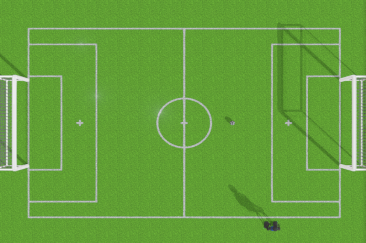
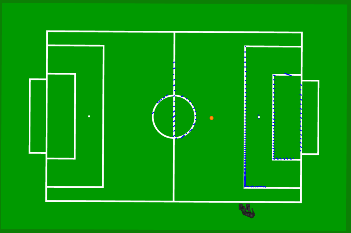
Localisation is the process of estimating the position and orientation of the robot relative to the soccer field. The NUbots codebase uses a Particle Filter approach to estimate the robot's position and orientation relative to the soccer field.
Spaces/Reference Frames
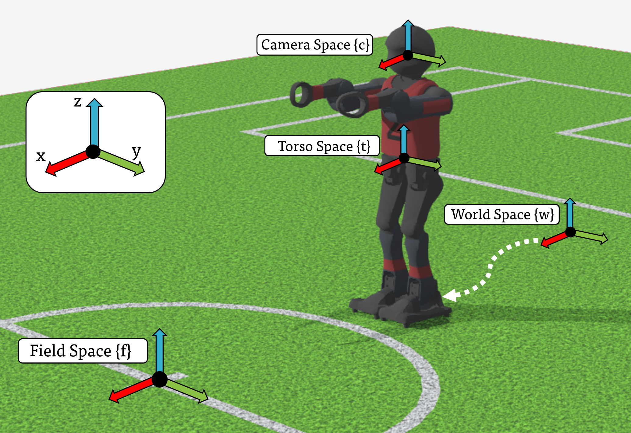
The NUbots codebase uses a number of different reference frames (spaces) for different purposes. The following is a list of the commonly used spaces in the codebase.
| Space | Letter | Description |
|---|---|---|
camera | C | Located at camera (left/right) with x pointed "outwards", y to the "left" and z "up" |
world | W | Located on the ground below the robot on startup. (Fixed inertial frame) |
torso | T | Fixed midway between the robots hip yaw joints, with x "forward", y to the "left" and z "up" |
robot | R | Located directly beneath torso projected onto the ground, with x "forward", y to the "left" and z "up" |
field | F | Located at the centre circle of the field, with x pointing towards the "own" goal and z "up" |
Particle Filter Localisation
The FieldLocalisation module is a primary component of the NUbots localization system. It uses a Particle Filter approach to estimate the robot's position and orientation relative to the soccer field. See notebook Particle Filter Localisation for more details on Monte-Carlo localisation.
Initialisation
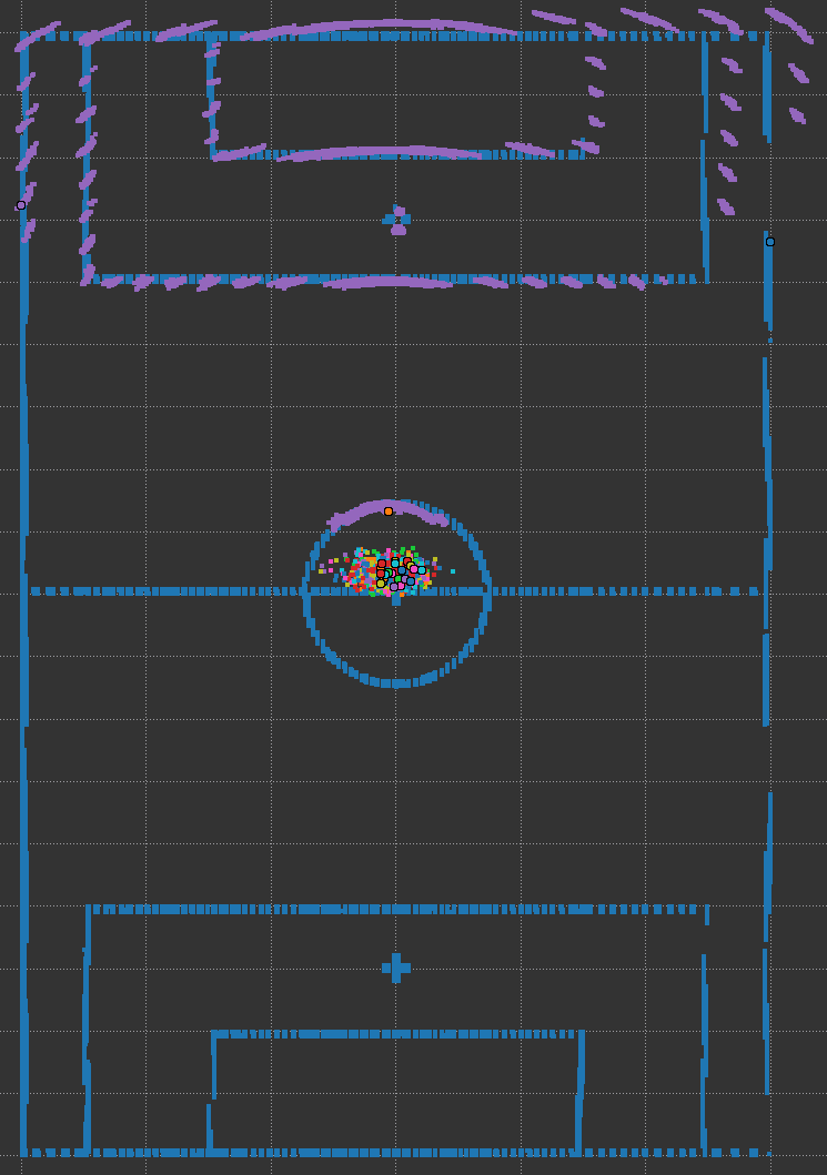
At initialisation, n particles are sampled from a multivariate normal distributions on either side of the field facing towards the centre, to produce initial hypothesis' of the robots starting position. For example, a visual illustration of 20 particles being initialized around the centre of the field is shown below.
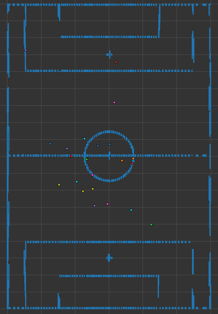
Additionally, a discretized field line distance map is pre-computed at startup which encodes the minimum distance to an occupied cell (field line). An example of a field line map is shown below.

Measurement Update
The measurement update involves weighting each particle. The general idea is to weight particles higher if field line point observations are closer to field lines. For each particle, the field line point observations are projected onto the field plane (using Odometry) and mapped into an index in the field line distance map. The weight of the particle is then calculated using simple inverse function:
where is the weight of the th particle, is the total sum of distance values squared obtained from the map for all field line point observations, and is machine epsilon to prevent numerical issues.
Time Update
Since the latest Odometry information is used within the measurement update, the time update does not directly involve propagating particles forward in time using any motion model. Instead, the time update involves simply adding noise to the particles to simulate the uncertainty in the robot's motion and resampling the particles.
Resampling refines the set of particles in Particle Filter localization based on their calculated weights.
-
Normalize Weights: Particle weights are adjusted so their sum is 1, ensuring each represents its proportional likelihood.
-
Particle Selection: Using the normalized weights, particles are probabilistically chosen. The original set of particles is replaced with the newly resampled set, now skewed towards more likely positions and orientations of the robot.
Below is after a few iterations of the filter after the measurement update and resampling is shown below
